
TOP

PRODUCTS
 Home > Products
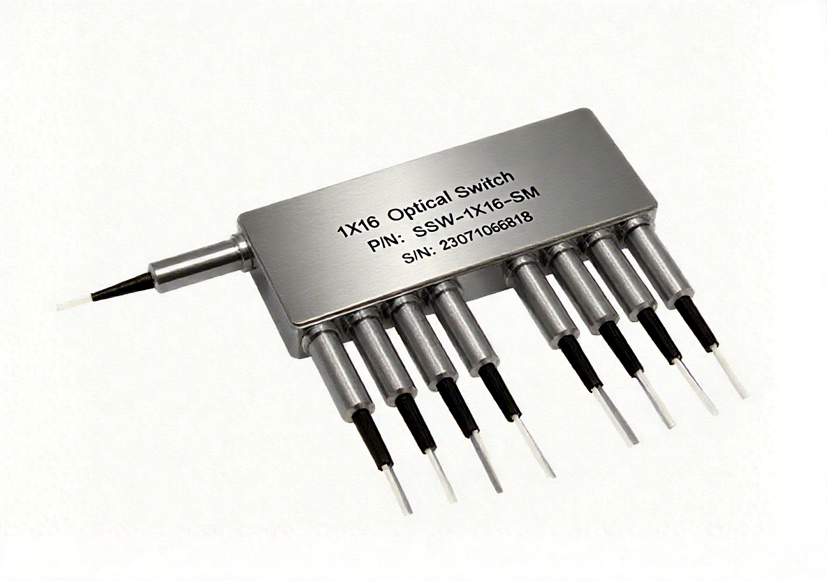


1×16 Solid-state fiber optical switch connects optical channels by redirecting an incoming optical signal into a selected output fiber. This is achieved using non-mechanical configurations and activated via an electrical control signal. Latching operation preserves the selected optical path after the drive signal has been removed. The all solid state 1x16 fiberoptic switch features low insertion loss, high extinction ratio, high channel isolation, and extremely high reliability and repeatability. It is designed to meet the most demanding switching requirements of continuous operation without failure, longevity, operation under shock/vibration environment and large temperature variations, and fast response time.
1x16 Switch | Min | Typical | Max | Unit |
Operation Wavelength | 1520 | 1550 | 1580 | nm |
1295 | 1310 | 1325 | nm | |
Insertion Loss | 1.5 | 2.5 | dB | |
Uniformity | 0.7 | 1.0 | dB | |
Cross Talk | 40 | 50 | dB | |
Return Loss | 50 | dB | ||
Polarization Dependent Loss | 0.15 | 0.4 | dB | |
Polarization Mode Dispersion | 0.2 | Ps | ||
Switch Speed (Rise, Fall) | 50 | 200 | us | |
Repetition Rate | 2K | Hz | ||
Durability | 1011 | cycle | ||
Optical Power Handling | 300 | 500 | mW | |
Switch Type | Solid-State Latching | |||
Operating Temperature | -5 | 65 | oC | |
Storage Temperature | -40 | 85 | oC | |
Fiber Type | Corning SMF-28 | |||
Mechanical Dimensions (Unit: mm)

Electrical Driving Information
Each switching point is actuated by applying a voltage pulse. Applying one polarity pulse, one light path will be connected and latched to the position. Applying a reversed polarity pulse, another light path will be connected and latched to the position after pulse removed.
Parameter | Minimum | Typical | Maximum | Unit |
Resistance (each group) | 15 | 18 | 22 | Ω |
Switch Voltage | 2.5 | 2.5 | 2.75 | V |
Pulse Duration | 0.2 | 0.3 | 0.5 | ms |
Driving kit with USB and TTL interfaces and WindowsTM GUI is available. We also offer RS232 interface as an option – please contact CORERAY sales.
Electric Driving Table
Optical Path | PG1 * | PG2 | PG3 | PG4 | PG5 | PG6 | PG7 | PG8 | PG9 | PG10 | PG11 | PG12 | PG13 | PG14 | PG15 | PG16 | |||||||||||||||||
1 | 2 | 3 | 4 | 5 | 6 | 7 | 8 | 9 | 10 | 11 | 12 | 13 | 14 | 15 | 16 | 17 | 18 | 19 | 20 | 21 | 22 | 23 | 24 | 25 | 26 | 27 | 28 | 29 | 30 | 31 | 32 | ||
IN→P1 | + | - | + | - | + | - | + | - | + | - | + | - | - | + | - | + | - | + | NC | NC | NC | NC | NC | NC | - | + | - | + | - | + | - | + | |
IN→P2 | - | + | - | + | + | - | + | - | + | - | + | - | - | + | - | + | - | + | NC | NC | NC | NC | NC | NC | - | + | - | + | - | + | - | + | |
IN→P3 | + | - | + | - | - | + | + | - | + | - | - | + | + | - | - | + | - | + | NC | NC | NC | NC | NC | NC | - | + | - | + | - | + | - | + | |
IN→P4 | - | + | - | + | - | + | + | - | + | - | - | + | + | - | - | + | - | + | NC | NC | NC | NC | NC | NC | - | + | - | + | - | + | - | + | |
IN→P5 | + | - | + | - | - | + | - | + | + | - | - | + | - | + | + | - | - | + | NC | NC | NC | NC | NC | NC | - | + | - | + | - | + | - | + | |
IN→P6 | - | + | - | + | - | + | - | + | + | - | - | + | - | + | + | - | - | + | NC | NC | NC | NC | NC | NC | - | + | - | + | - | + | - | + | |
IN→P7 | + | - | + | - | - | + | - | + | - | + | - | + | - | + | - | + | + | - | NC | NC | NC | NC | NC | NC | - | + | - | + | - | + | - | + | |
IN→P8 | - | + | - | + | - | + | - | + | - | + | - | + | - | + | - | + | + | - | NC | NC | NC | NC | NC | NC | - | + | - | + | - | + | - | + | |
IN→P9 | + | - | - | + | NC | NC | NC | NC | NC | NC | - | + | - | + | - | + | - | + | - | + | - | + | - | + | + | - | - | + | - | + | - | + | |
IN→P10 | - | + | + | - | NC | NC | NC | NC | NC | NC | - | + | - | + | - | + | - | + | - | + | - | + | - | + | + | - | - | + | - | + | - | + | |
IN→P11 | + | - | - | + | NC | NC | NC | NC | NC | NC | - | + | - | + | - | + | - | + | + | - | - | + | - | + | - | + | + | - | - | + | - | + | |
IN→P12 | - | + | + | - | NC | NC | NC | NC | NC | NC | - | + | - | + | - | + | - | + | + | - | - | + | - | + | - | + | + | - | - | + | - | + | |
IN→P13 | + | - | - | + | NC | NC | NC | NC | NC | NC | - | + | - | + | - | + | - | + | + | - | + | - | - | + | - | + | - | + | + | - | - | + | |
IN→P14 | - | + | + | - | NC | NC | NC | NC | NC | NC | - | + | - | + | - | + | - | + | + | - | + | - | - | + | - | + | - | + | + | - | - | + | |
IN→P15 | + | - | - | + | NC | NC | NC | NC | NC | NC | - | + | - | + | - | + | - | + | + | - | + | - | + | - | - | + | - | + | - | + | + | - | |
IN→P16 | - | + | + | - | NC | NC | NC | NC | NC | NC | - | + | - | + | - | + | - | + | + | - | + | - | + | - | - | + | - | + | - | + | + | - | |
PG1: Pin Group 1; NC: No electronic connection.
Routing

Ordering Information: SSW-A-B-C-D-E-F-G
A | B | C | D | E | F | G | |
Type | Wavelength | Switch | Package | Fiber Type | Fiber Length | Connector | |
116=1x16 000=Special | 3=1310 5=1550 0=Special | 2=Dual Stage 0=Special | 1=Standard 0=Special | 1=SMF-28 0=Special | 1=Bare fiber 3=900µm loose tube 0=Special | 1=0.25m 2=0.5m 3=1.0m 0=Special | 1=None 2=FC/PC 3=FC/APC 4=SC/PC 5=SC/APC 6=ST/PC 7=LC 8=Duplex LC 9=MTP 0=Special |
Example Model:SSW-116-3-2-1-1-1-1-1
Description: Type: 1x16, Wavelength: 1310, Switch: Dual Stage, Package: Standard, Fiber Type: SMF-28 Bare fibe , Fiber Length: 0.25m, Connector: None .
For custom components, please provide detailed requirements.


Scan to add on WeChat


 中文
中文 EN
EN