
TOP

PRODUCTS
 Home > Products
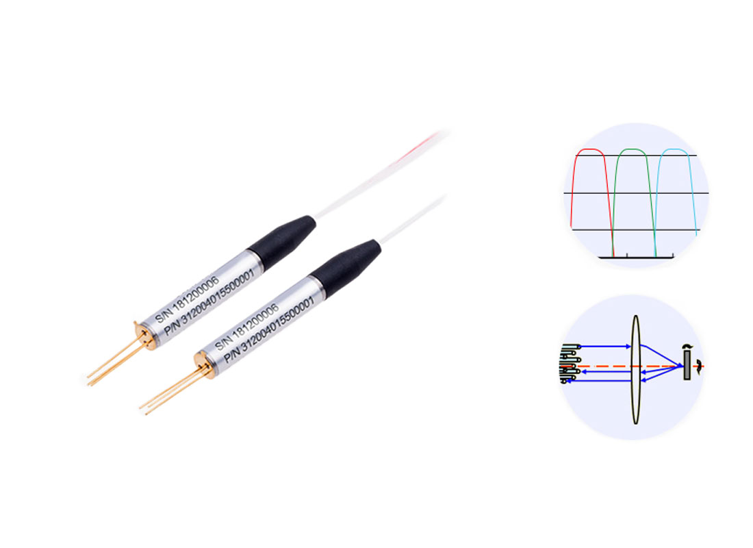


The MSW-2×N optical switch (hereinafter referred to as the MEMS optical switch) is a multi-channel optical path switching module. It utilizes electrostatically actuated micro-mirror technology, featuring compact size, fast response, and stable performance. It is widely applicable in optical communication and testing systems. The optical path schematic is as follows:

Applications:
l Multi-channel optical monitoring in optical transmission systems
l LAN multi-source/detector automatic switching, dynamic multi-point optical sensing systems
l Automated testing of fibers, optical components, networks, and field engineering cables in optical testing systems
l Optical device alignment
Features:
l Fast switching speed, low loss, high reliability, and long lifespan
l Compact size, simple TTL control interface
l Modular design, low insertion loss
Specifications:
Parameter | Value | |
Operating Wavelength (nm) | 850/1310 ,1260~1650 | |
Fiber Type (µm) | Single-mode, Multi-mode, Polarization-Maintaining (PM) | |
Extinction Ratio① (dB) | ≥18 | |
Insertion Loss (dB) | ≤0.8 (N=2~12),≤1.0(N=12~24) ≤1.2(N=24~32),≤1.5(N=32~64) | |
Return Loss (dB) | SM:≥50 MM:≥30 | |
Crosstalk (dB) | SM | ≥50(N≤32),≥45(32<N≤64) |
MM | ≥30(N≤16),≥25(16<N≤32) | |
Repeatability (dB) | ≤±0.02 | |
Switching Time (ms) | Typ :5ms | |
Switching Lifetime | ≥109 cycles | |
Max. Optical Power (mW) | 500 | |
Operating Temperature (°C) | -10~+70 | |
Storage Temperature (°C) | -40~+80 | |
Control Interface | TTL、RS232 | |
Operating Voltage (V) | 5V | |
Dimensions (mm) | 25*16*8 | |
Specifications apply to polarization-maintaining (PM) models.
Dimensions (mm):


Pin Definitions
Pin | Pin Name | Type | Level | Description | |
M3,4,5 | M1,2 | ||||
1 | 5 | D0 | IN | LVTTL | TTL mode: Data bit D0 input |
2 | / | D5 | IN | LVTTL | TTL mode: Data bit D5 input |
3 | 2 | VCC | Power IN | / | DC +5V power supply |
4 | / | D7 | IN | LVTTL | TTL mode: Data bit D7 input |
5 | / | D6 | IN | LVTTL | TTL mode: Data bit D6 input |
6 | 4 | GND | Power IN | Ground | |
7 | 10 | D4 | IN | LVTTL | TTL mode: Data bit D4 input |
8 | 12 | D1 | IN | LVTTL | TTL mode: Data bit D1 input |
9 | 6 | TXD | / | / | Module UART_TX |
10 | 7 | RXD | / | / | Module UART_RX |
11 | 9 | D2 | IN | LVTTL | TTL mode: Data bit D2 input |
12 | 13 | D3 | IN | LVTTL | TTL mode: Data bit D3 input |
13 | 8 | BUSY | OUT | LVTTL | High level indicates busy; control invalid |
14 | 1 | ALARM | OUT | LVTTL | High level indicates fault |
15 | 3 | /STROBE | IN | LVTTL | TTL mode: Falling edge trigger |
16 | 14 | /RESET | IN | LVTTL | Reset (low active, pulse width ≥10 ms) |
Model Selection: MSW-2×N-A-B-C-D-E-F
N | A | B | C | D | E | F |
Ports | Fiber Type | Wavelength | Buffer Tube | Fiber Length | Connector | Package |
2-256 | SM:9/125um M5:50/125um M6:62.5/125um M10:105/125um PM:PM Fiber | 85:850nm 13: 1310nm 14: 1490nm 15: 1550nm | 25:250um 50:500um 90:900um | 05:0.5m 10:1.0m 12:1.2m | OO:None FP: FC/PC FA: FC/APC SP: SC/PC SA: SC/APC LP: LC/PC LA: LC/APC MPO | M1:PCB M2:39*24*13.5 M3:90*55*12 M4:100*100*12 M5:110*141*12 |


Scan to add on WeChat


 中文
中文 EN
EN